When you use Edgewall on multiple DXF/DWG lines, you position and then place each wall individually. ICE walks you through the process of positioning each wall. The Edgewall assistance text in the top-left corner of ICE 2D plan view tells you how many DXF/DWG lines you have selected. It also tells you how which line you are positioning, for example, "Line 3 of 11." For example, if you you are using Edgewall on 11 lines and you are on line 2, you know that you have nine more lines to Edgewall.
When you use Edgewall on multiple DXF/DWG lines, intersecting i-Lines extend or retract to meet each other and snap together, and the intersecting lines become yellow. If intersecting lines do not snap, you may have to adjust the snap strength. The default snap strength of 1" will work for most intersecting i-Lines. However, you may have to adjust these values.
To Apply Edgewall to Multiple DXF/DWG Lines
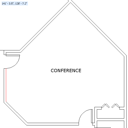
1.In ICE 2D plan view, click the first DXF/DWG line.
When you select the DXF/DWG line, it turns red.
2.Press and hold down on the CTRL key, and click the remaining lines.
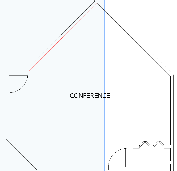
3.Release the CTRL key.
4.Right-click and choose Edgewall.
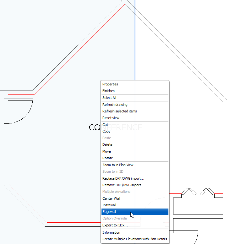
You see the Edgewall dialog box open.
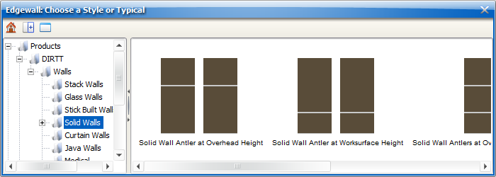
5.Find the i-Line style that you want to Edgewall.
6.To Edgewall, click the i-Line style that you want to use.
You see a preview of the i-Line on the edge of the selected DXF line. Assistance text appears in the top-left corner of ICE 2D plan view, telling you how to offset and rotate 180 and indicating the number of selected DXF lines and the line that you are placing.
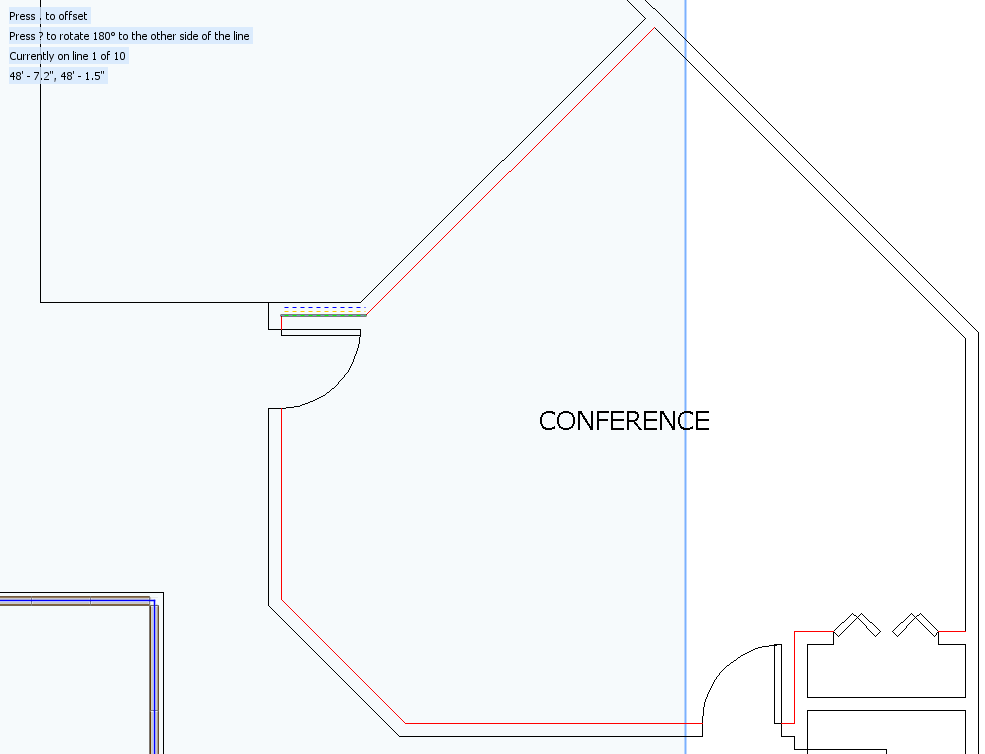
Tip: Before you start positioning and placing i-Lines on the DXF/DWG lines, make sure that you have all of the selected DXF/DWG lines in view. When you have all the lines in view, you can easily position and place each wall.
7.If you want to change offset of the wall relative to the selected DXF/DWG line, press the . key.
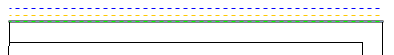
This example image shows the wall before using Offset. The wall lies between two DXF/DWG lines and the blue line lines:

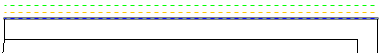
This example image shows the same wall after using the offset function. The wall now lines up with the outside edge of the DXF/DWG line:
8.If you have a wall that is different on side A and side B and you want to rotate the wall 180 degrees so that you can change the side of the i-Line that lines up with the DXF line, press the ? key.
This example image shows the wall before using the rotate 180 function:
This example image shows the i-Line after using the rotate 180 function. The wall has rotated 180 degrees and now lines up with the outside edge of the DXF/DWG line:
9.Press Enter.
You see the next i-Line preview line appear. In the top-left corner of ICE 2D plan view, the line number changes. In this example image, we now place the second line, "Line 2 of 10":
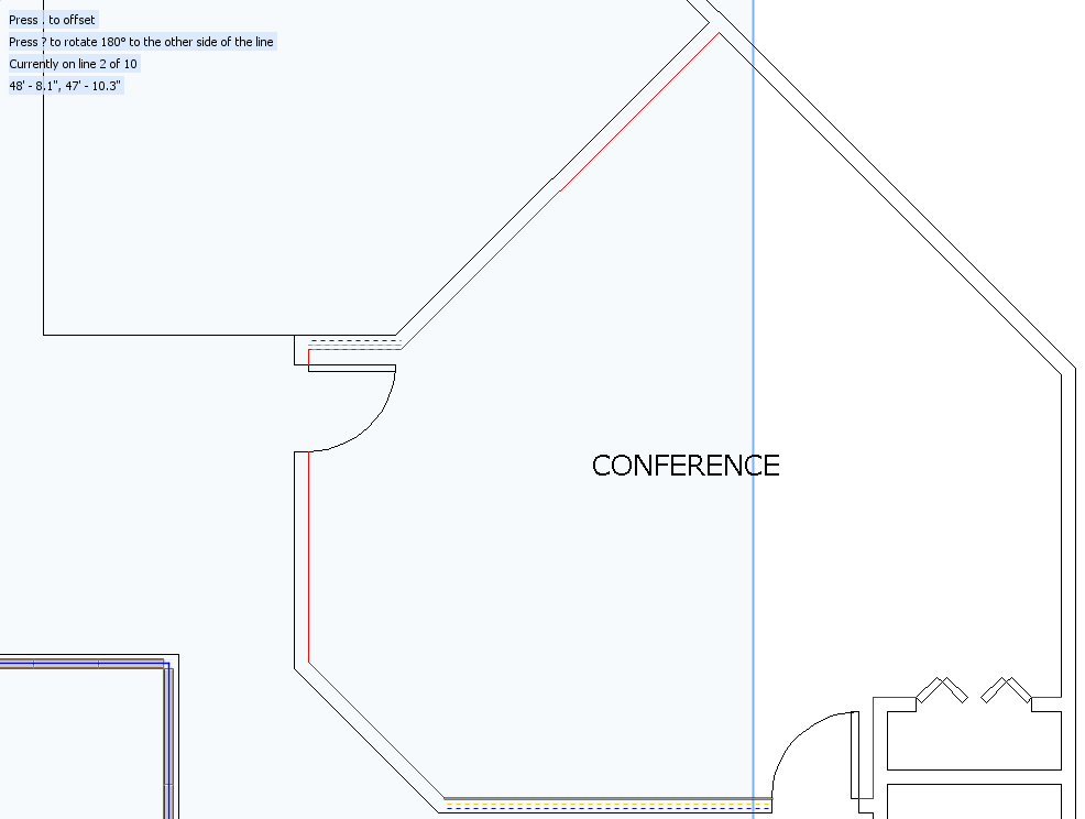
If the next DXF/DWG line intersects with a wall that you have already placed or an existing wall, the wall that you are placing extends or retracts and snaps to meet that wall and the walls become yellow:
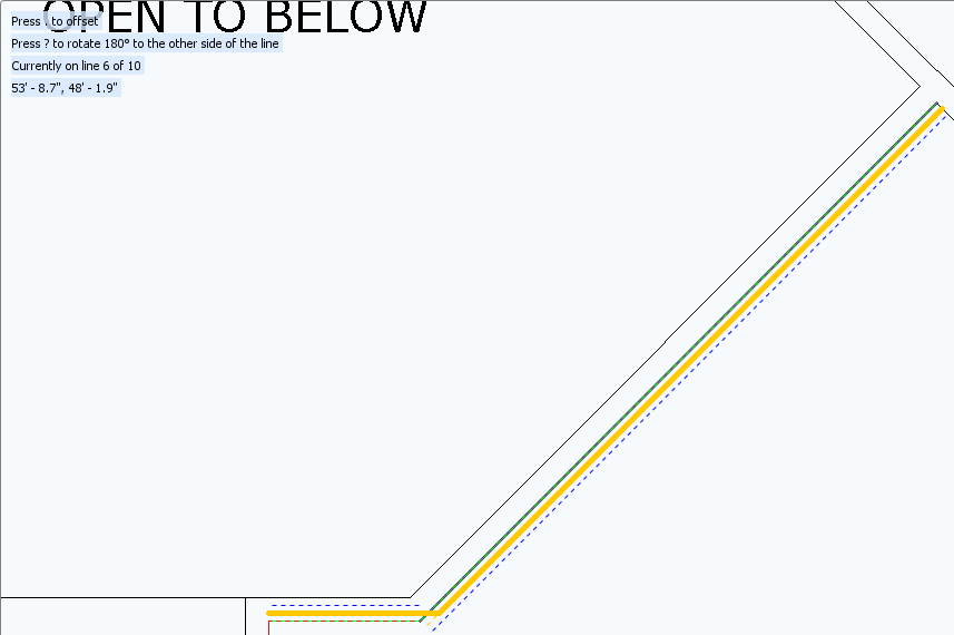
Tip: If intersecting lines do not snap, you may have to adjust the snap strength. The default snap strength of 1" will work for most intersecting walls. However, you may have to adjust these values.
10.Repeat steps 7-8 until you have placed all of the walls.
11.If you want to exit out of the Edgewall command before you finish placing all your i-Lines, hit ESC or right click.
When you press ESC or right-click, the i-Lines that you have already positioned appear in ICE 2D plan view. For example, if you position 4 of tepress
Related Links: