Leverage ICEcad* to draw accurate faceted DIRTT Wall Layouts.
What Are We Talking About?
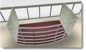
Your client wants a "curved" front to their DIRTT Wall Conference room. DIRTT Walls can be used as facets to create this effect. A few simple AutoCAD commands makes laying this out in ICE a snap.
What's in it for you:
•Quickly layout more complex designs •Control module sizes to achieve the best look for your clients.
How to do it:
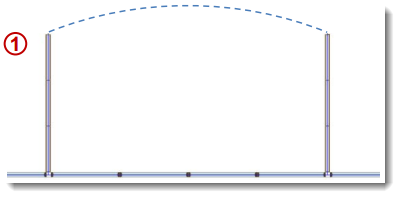
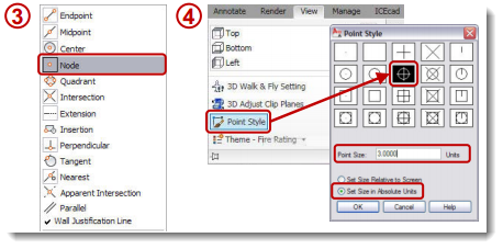
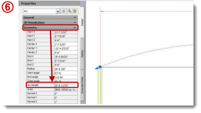
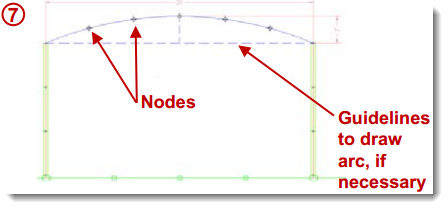
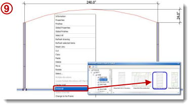
1.In ICE, draw as much of the layout surrounding the faceted wall as you can. In this example, the two side walls and the perimeter have been drawn. 3.Once linked, in AutoCAD, make sure Object Snapping to Nodes is turned on. [OSNAP] 4.In order to see the Nodes you are about to create, go to your Point Styles [DDPTYPE] and change the settings to match image 4. This makes them visible and set to a comfortable size. 5.Draw an AutoCAD arc that represents the centerline of the DIRTT Wall. Besure to snap to the end of the i-lines™ at both sides. 6.Highlight the arc and call up Properties. Note the arc length. Use this distance to determine the number of facets that do not exceed the maximum width of your wall type (glass: 60", solid or stacked: 48"). 7.Type DIVIDE at the command prompt, then Enter. Select the arc, Enter then type the number of facets desired and Enter. You should see Nodes along the arc. 8.Open the ICE Palette, go to the Geometry folder and select Line. Draw ICE Lines from Node-to-node (you may need to zoom in to ensure you are snapping to the correct points along the arc). 9.Back in ICE, highlight the lines you just drew in ICEcad, right-click to InstaWall and select the Wall Style to use for the faceted front. 10.Open ICE 3D and marvel at the beauty.
*Requires an ICEcad license, contact sales@ice-edge.com for more information. |
|