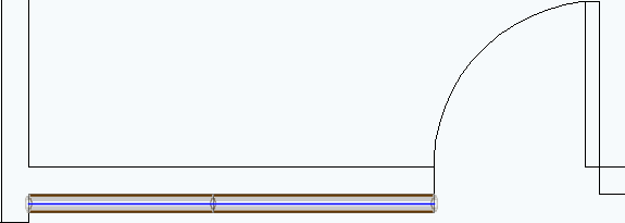
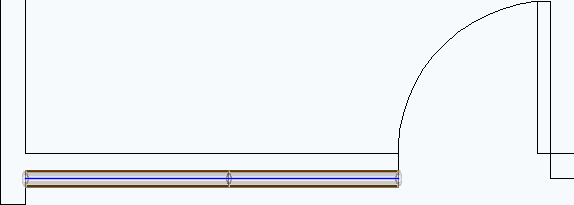
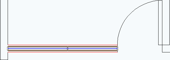
When you import a base plan, DXF and DWG lines appear in ICE. ICE has three features that you allow you to use these lines to place i-Lines: Center Wall, Edgewall, and Instawall.
The chart below summarizes the differences between Edgewall, Center Wall, and Instawall:
|
What can it do? |
Preview |
Position |
Select Multiple Lines |
Use in ICE 2D |
Use in ICEcad |
Edgewall |
Place a i-Line so that one of its sides lines up with the edge of a DXF/DWG line. |
Yes |
Yes |
Yes |
Yes |
No |
Center Wall |
Place a i-Line between two parallel DXF/DWG lines. |
No |
No |
Yes |
Yes |
No |
Instawall |
Turn a DXF/DWG line into a i-Line. The line becomes the i-Line, so i-Line is centered on the line. |
No |
No |
Yes |
Yes |
No |

Edgewall

Instawall

Center Wall
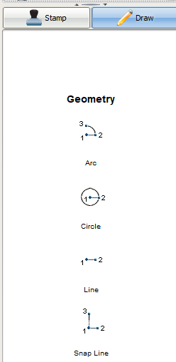
Geometry Lines
You can also use the Line and Snap Line tools to place an i-Line with Edgewall, Center Wall, and Instawall.

However, when you use Edgewall or Center Wall to place an i-Line, the line that you used to place the i-Line remains in your layout. If you use Snap Line to create these lines, they may end up having unwanted interactions with the i-Lines that you place. Therefore, we don't recommend that you use Snap Lines to Edgewall or Center Wall.
Topics: