With the Ceiling Thief, you can position the drop ceiling support extrusions directly above a full height door. When the Ceiling Thief is positioned above a full height door, your drop ceiling support accommodates a ceiling that appears directly above the door with no stack tile in between.
Note: Ceiling support extrusions provide perimeter support for drop ceilings. However, they do not include drop-in ceiling tiles, t-bars, and other ceiling components.
To a Specify Ceiling Thief Barn Door without a Stack Tile
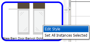
1.In the Product Palette, find a barn door style with a stack solid tile above it, and right-click to choose Edit Style.
This example shows the Glass Barn Door Barivot Goldie, a glass Barn Door with a stack solid tile:
The Style Manager opens.
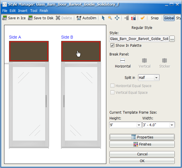
2.To select the solid tiles for both sides of the door, hold down the CTRL key, and click Side A and then Side B.
This example image shows the stack solid tiles for Side A and Side B selected:
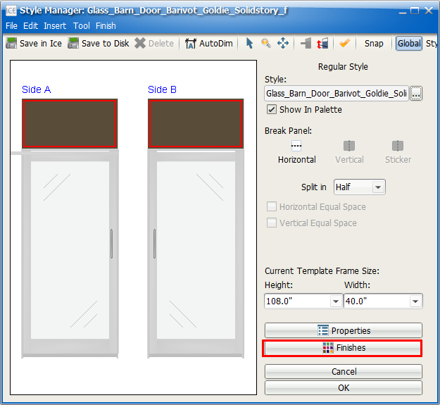
3.To open the Finishes tab of the Properties and Finishes Editor, click Finishes.
This image shows the Finishes button highlighted in the Style Manager.
The Properties and Finishes Editor opens to the Finishes tab.
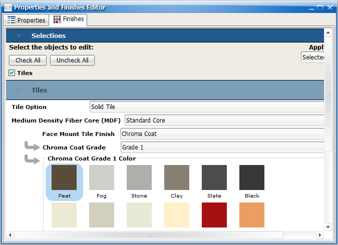
4.Under Select the Objects to Edit, confirm that a check mark appears in the box beside Tiles.
This image shows the Finishes tab of the Properties and Finishes editor with the box beside Tiles checked:
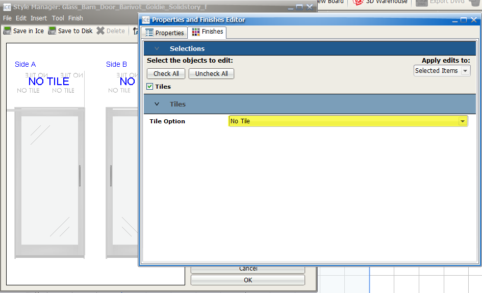
5.Under Tiles, in the Tile Option menu, choose No Tile.
In the Style Manager, your the Solid tile above the door updates to No Tile. This image shows the No Tile option selected in the Properties and Finishes Editor and No Tile applied to the Barn door style:
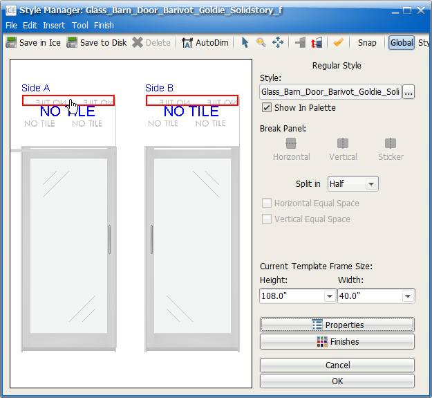
6.In the Style Manager, double-click the top extrusion for the stack wall module that is above the door.
When you double-click, you select the extrusion for both sides of the wall. This image shows the top extrusion selected on Side A and Side B:
7.To open the Properties Editor, click Properties.
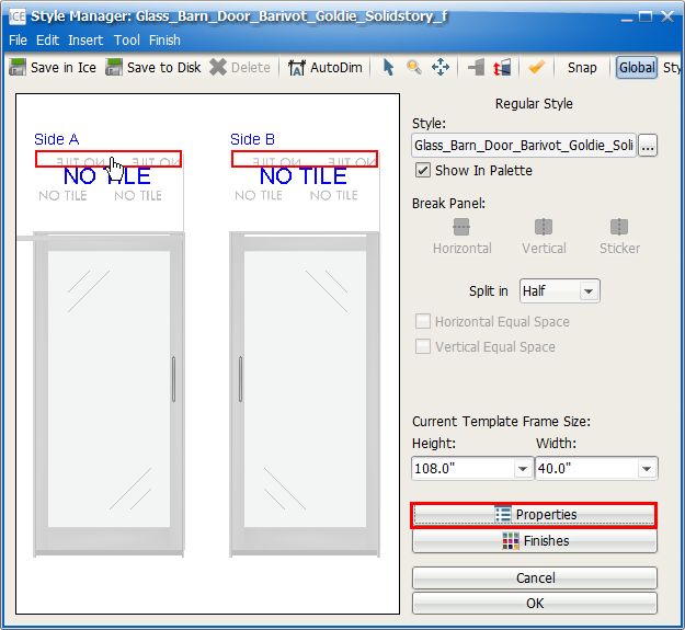
The Properties Editor opens.
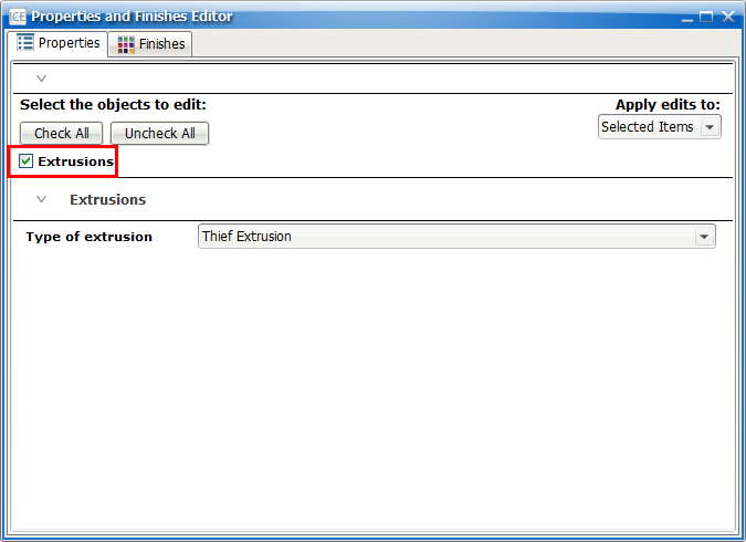
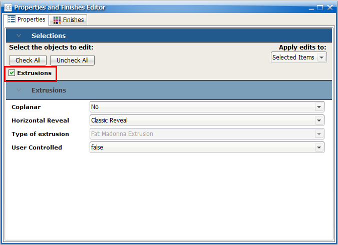
8.Under Select the objects to edit, confirm that a check mark appears in the box beside Extrusions.
This image shows the box beside Extrusions checked:
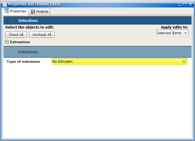
9.Under Extrusions, in the Type of extrusion menu, choose No Extrusion.
This example shows No Extrusion selected in the Properties Editor:
10.In the Style Manager, double-click the bottom extrusion for the stack wall module that is above the door.
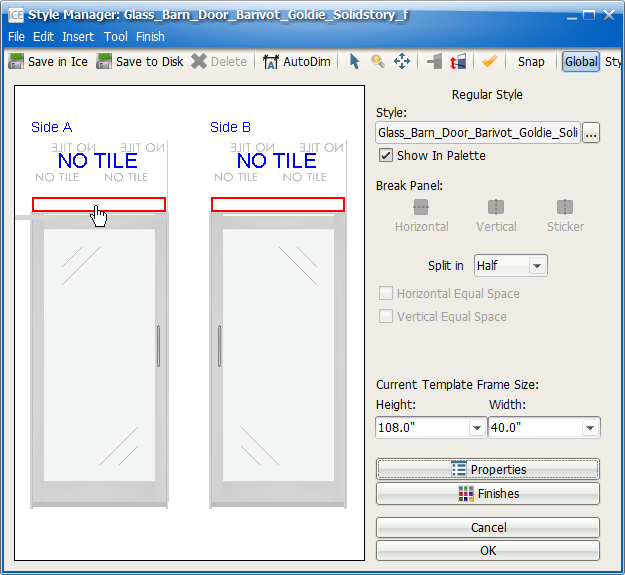
When you double-click, you select the extrusion on both sides of the door.
Tip: If you are unable to select the correct extrusions when you double-click on one side (for example, Side A), try double-clicking the same extrusion on the other side of the door (for example, Side B).
This image shows the bottom extrusions for the stack wall module selected:
11.To open the Properties Editor, click Properties.
12.In the Properties Editor, under Select the objects to edit, confirm that a check mark appears in the box beside Extrusions.
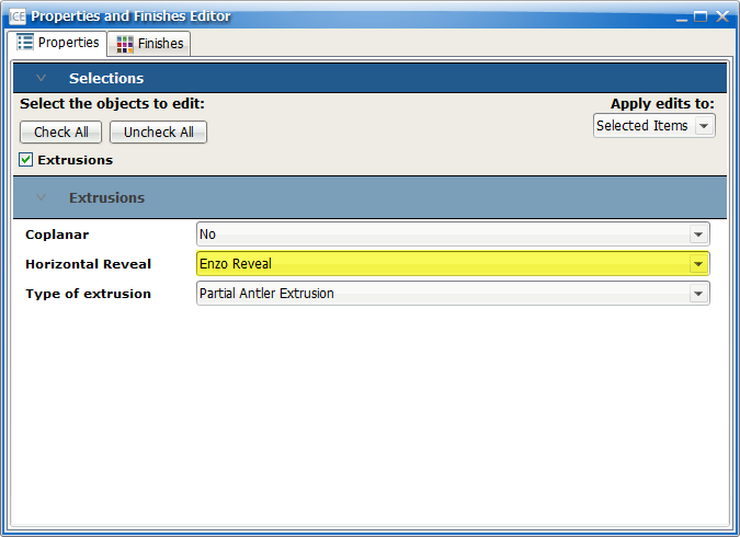
13.Under Extrusions, in the Horizontal Reveal menu, choose Enzo Reveal.
This image shows the Enzo Reveal selected in the Horizontal Reveal menu:
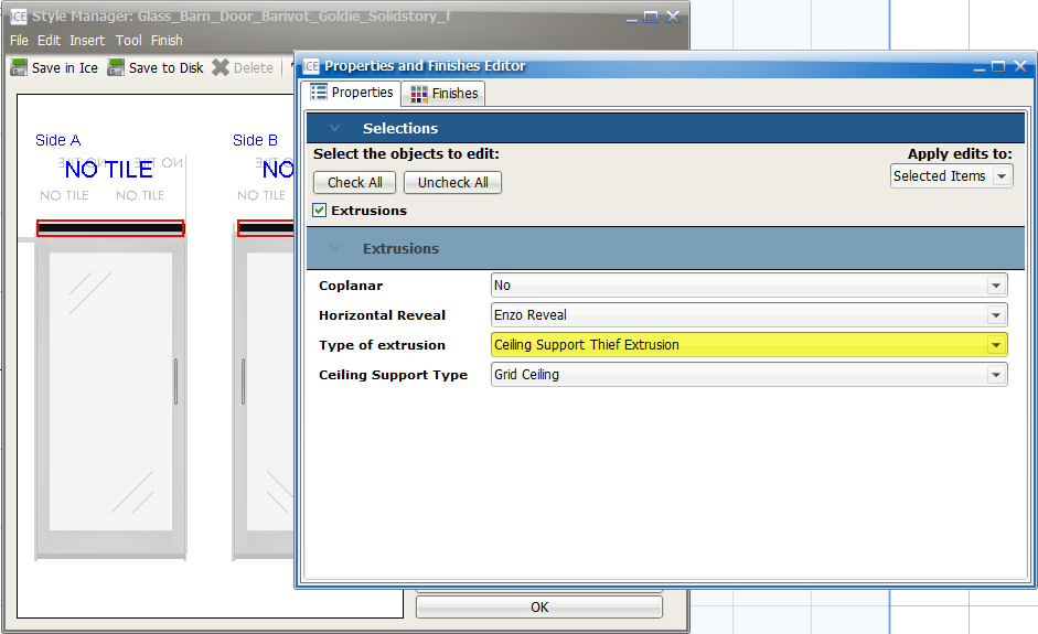
14.In the Type of extrusion menu, choose Ceiling Support Thief Extrusion.
In the Style Editor, your door style updates to show the Ceiling Thief Extrusion. This example image shows the Ceiling Support Thief Extrusion in the Properties Editor and on the door style in the Style Manager:
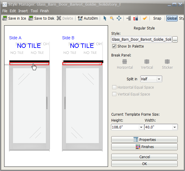
15.In the Style Manager, on Side A or Side B, click the door header extrusion.
When you double-click on one side of the door header extrusion, you select it on both sides of the door. This image shows the door header extrusion selected on Side A and Side B:
16.To open the Properties Editor, click Properties.
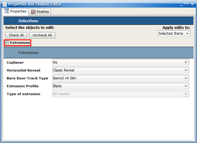
17.In the Properties Editor, under Select the objects to edit, confirm that a check mark appears in the box beside Extrusions.
This example image shows the box beside Extrusions checked. The Extrusions section appears under the Selections section:
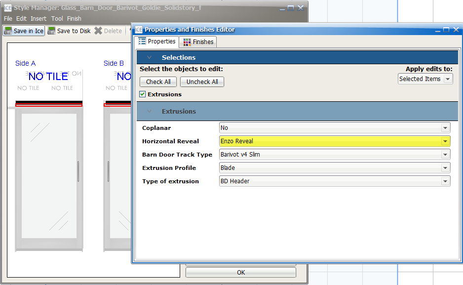
18.Under Extrusions, in the Horizontal Reveal menu, choose Enzo Reveal.
In the Style Manager, the door header updates to show the Enzo reveal. This image shows Enzo Reveal in the Horizontal Reveal menu and on the door style:
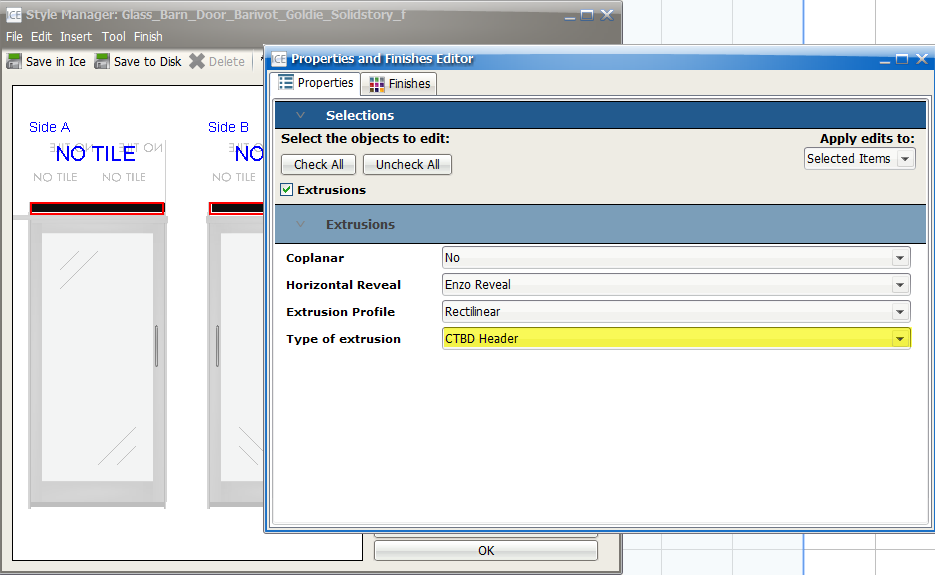
19.In the Type of extrusion menu, choose CTBD Header.
In the Style Manager, the door header updates to show the CTBD Header. This image shows the CTBD Header applied in the Style Manager and selected in the Properties Editor:
20.In the Style Manager, click Edit Multi-style layout.
This image shows the Edit Multi-style layout button highlighted red:
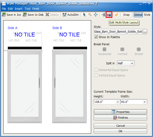
In the Style Manger, the multi-style layout opens.
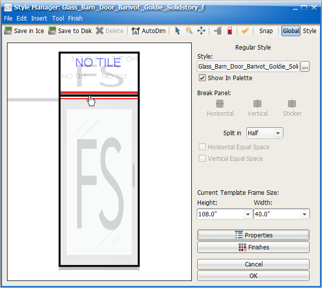
21.Click the stack split line.
This image shows the stack split line selected:
22.To open the Properties Editor, click Properties.
23.In the Properties Editor, under Select the objects to edit, confirm that a check mark appears in the box beside Other.
This image shows a check mark in the selection box beside Other. The Other section appears under the Selections section:
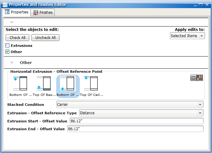
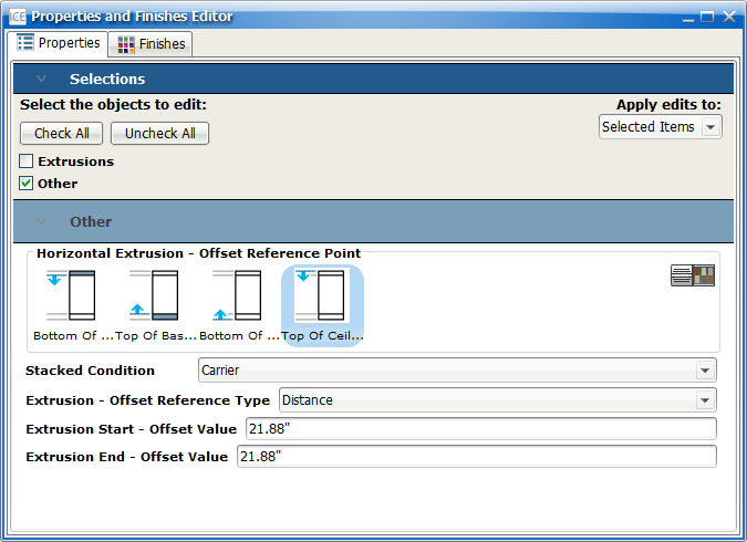
24.Under Horizontal Extrusion – Offset Reference Point, click Top of Ceiling.
The Extrusion Start and Extrusion End offset values update to reflect the new reference point. This image shows the Top of Ceiling Reference Point selected:
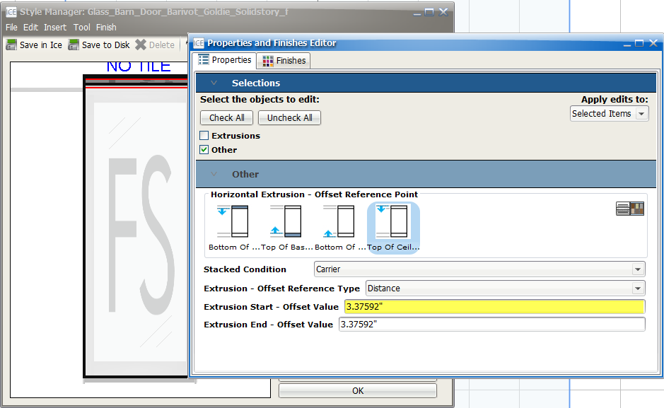
25.In the Extrusion Start – Offset Value field, type 3.3759191”.
The Extrusion End - Offset Value field updates to reflect the value that you typed. In the Style Manger, the stack split line moves up towards the top of the door style. This image shows the updated properties in the Properties Editor and the shifted stack split line in the Style Manager:
26. Once you finish creating your style, save it in the the Style Manager, and it appears in the ICE Product Palette.
Related Links:
•Specifying a Ceiling Thief on a Solid over Solid Wall
•Specifying Ceiling Support Extrusions for Different Ceiling Heights