In the Style Manager, you can specify Ceiling Antler ceiling perimeter support extrusion with a solid over solid stack style. After you create and save a wall style with a Ceiling Antler, your style appears in the ICE Product Palette, and you can draw it in ICE 2D plan view.
Note: Ceiling support extrusions provide perimeter support for drop ceilings. However, they do not include drop-in ceiling tiles, t-bars, and other ceiling components.
To Specify a Ceiling Antler with a Stack Style
1.In the Product Palette, right-click on a non-stack wall style and choose Edit Style.
The style opens in the Style Manager.
2.In the Style Manager, click Edit Multi-Style Layout.
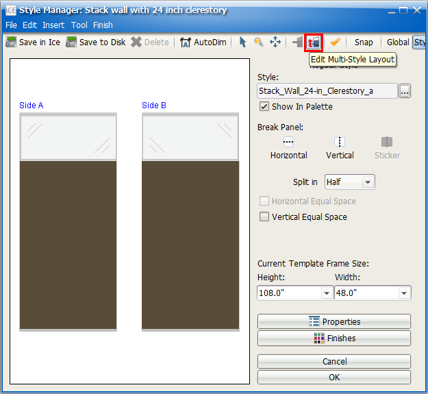
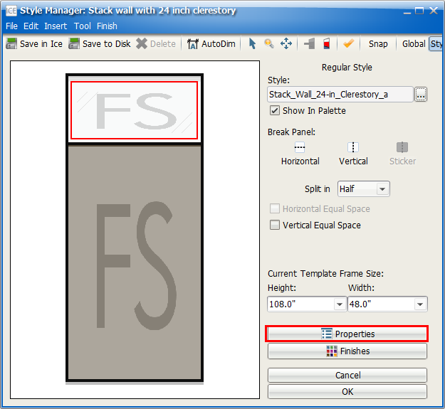
In the Style Manager, the Multi-style Layout opens. This image shows the example wall style in the Multi-style Layout:
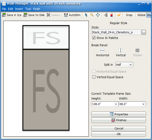
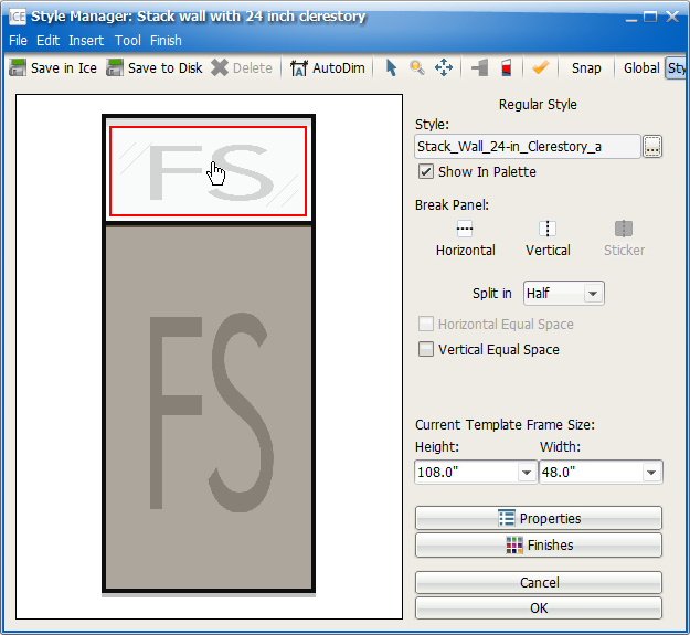
3.If your stack wall has a glass tile, click to select it and change it to solid.
This image shows a top glass tile selected:
4.Then, select Properties.
The Properties Editor opens.
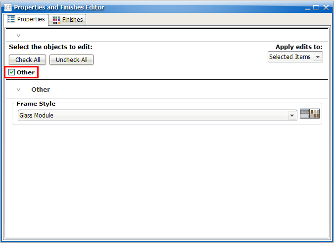
5.In the Properties Editor, under Select the objects to edit, confirm that a check mark appears in the box beside Other.
This image shows the Other check box selected:
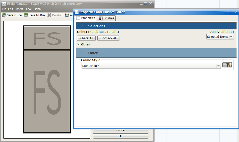
6.In the Frame Style menu, choose Solid Module.
In the Style Manager, the glass module updates to solid. This image shows Solid Module selected under Frame Style, and a solid module appears in the Style Manger:
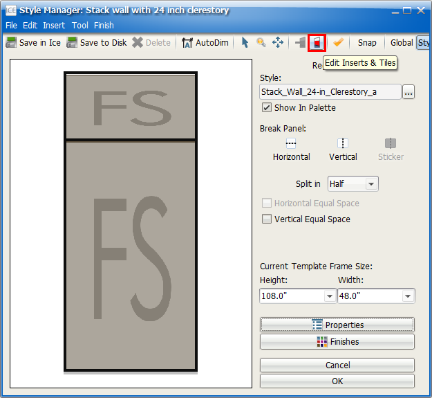
7.In the Style Manager, Click the Edit Inserts & Tiles icon to return to the standard view.

The Style Manager returns to the standard view. This example image shows the example style in the standard view:
8.On Side A or Side B, double-click the horizontal extrusion above the stack line.
When you double-click, you select the horizontal extrusion on both sides of the wall. This image shows the horizontal extrusions on Side A and Side B selected:
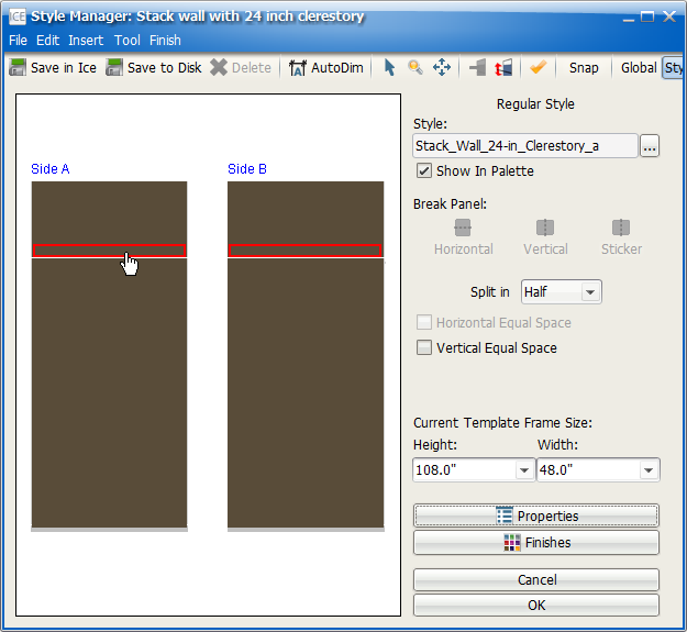
Caution: When you want to specify perimeter ceiling support extrusions with stack walls, you must select the horizontal extrusions on both sides of the wall to specify an Enzo revel. Even if you only want to add ceiling support extrusions to one side of the wall, you must change the horizontal reveal to Enzo for both sides of the wall.
9.Click Properties.
This image shows the Properties icon highlighted red.

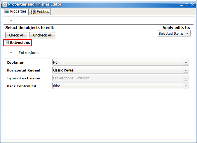
10.Under Select the objects to edit, confirm that a check mark appears in the box beside Extrusions.
This image shows the box beside Extrusions checked:
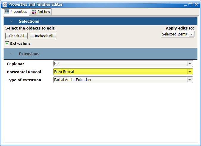
11.In the Horizontal Reveal menu, choose Enzo Reveal.
This image shows the Enzo Revel selected for the Horizontal Reveal:
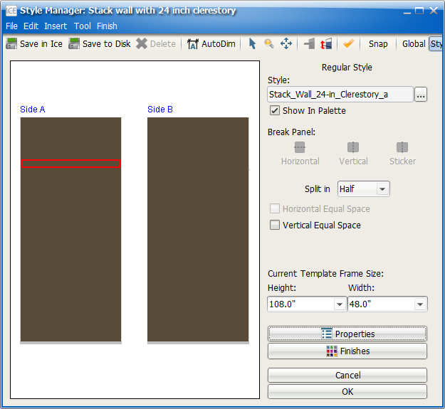
12.If you want to specify a Ceiling Antler extrusion for one side of your wall, return to the Style Manager, and click the extrusion on that side. If you want to specify Ceiling Antlers on both sides of your wall, continue to step 13
For example, in this image, only one the horizontal extrusion for Side A is selected, so only that side of the wall would receive a Ceiling Antler extrusion:
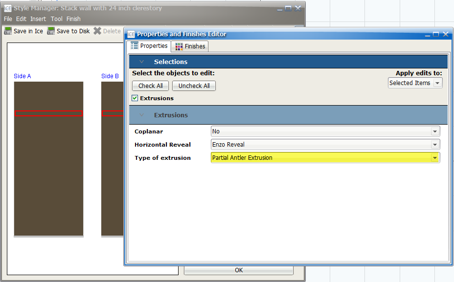
13.Under Type of Extrusion menu, choose the Ceiling Support Partial Antler Extrusion.
In the Style Manager, your style updates. This example image shows the updated style and the Partial Antler Extrusion selected in the Properties Editor:
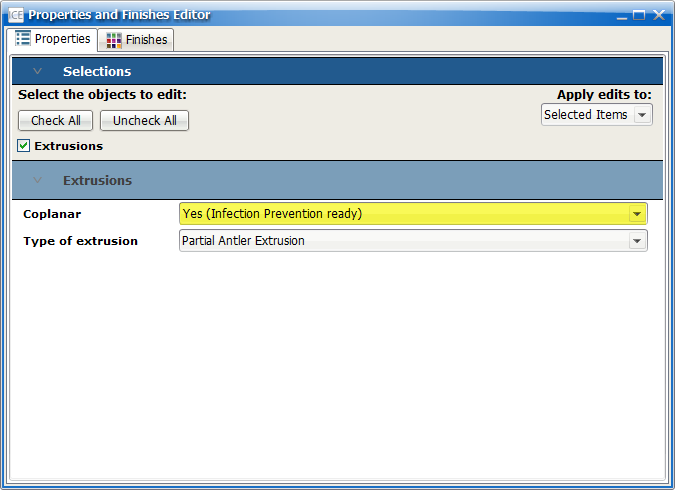
14.If you want to make your wall style Infection Prevention ready, in the Coplanar menu, choose Yes (Infection Prevention Ready).
This image shows Yes (Infection Prevention ready) selected in the Coplanar menu.
14.If you want to adjust the height of the Ceiling Support Antler Extrusion,
a.Under Horizontal Extrusion Offset Reference Point, choose a reference point.
b.Under Extrusion Start - Offset Value, type a new offset.
In this image, the reference point is Top Of Ceiling. To move the Ceiling Support Antler up, we would reduce the value in the Extrusion Start - Offset Value field (for example, 24.0").
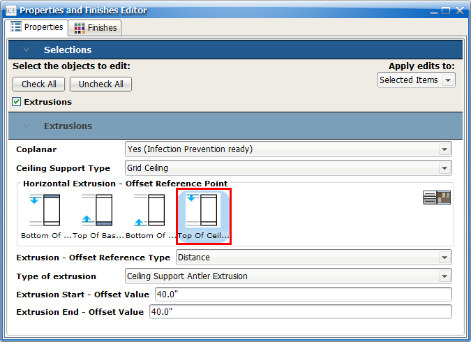
Tip: When using Top of the Ceiling as the Offset Reference Point, 7.83" (198.8mm) is the minimum Extrusion Start - Offset Value that you can enter. If you use a value that is lower than 7.83", Notification 130 appears.
15.Once you finish creating your style, save it in the the Style Manager, and it appears in the ICE Product Palette.
Related Links:
•Specifying a Ceiling Antler with a Non-stack Style
•Specifying Ceiling Support Extrusions for Different Ceiling Heights