In Current File Settings and the Properties Editor, you can change elevation settings and properties to refine the appearance of your elevations. You should edit Current File Settings before you insert elevations, and edit elevation properties in the Properties Editor after you insert elevations.
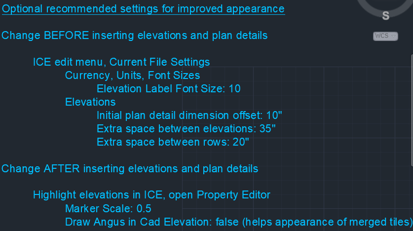
The DIRTT Wall Shop Drawing Template lists recommended elevation properties and settings beside the elevation section:

Although we recommend these refinement tools, you are not required to use them to prepare your file for Order Entry. .
We recommend that you change the following elevation settings in Current File Settings before you insert elevations:
•Elevation Label Font Size: Change to 10, making the labels that appear under elevations smaller (for example, Elevation A).
•Initial plan detail dimension offset: Change to to 10", modifying the spacing between the plan detail and its first dimension line.
•Extra space between elevations: Change to 35", modifying the horizontal spacing between elevations.
•Extra space between rows: Change to 20", modifying the vertical spacing between elevation rows.
We recommend that you change the following elevation settings in the Properties Editor after you insert elevations:
•Marker Scale: Change to 0.5, making the elevation markers in the plan smaller.
•Draw Angus in Cad Elevation: Change False, hiding extrusions on merged tiles.
Topics:
•Changing Elevation Label Font
•Changing Spacing Between Plan Detail Dimension
•Changing Spacing Between Elevation Rows
•Changing Spacing Between Elevations