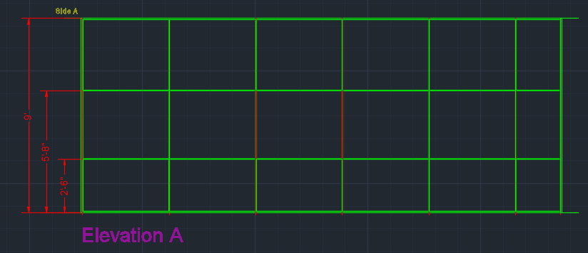
When you insert elevations in ICE 2D plan view or ICEcad, elevations and their associated dimension and labels appear on separate, identifiable layers in AutoCAD. Each part of the elevation, for example, labels, markers, dimensions, appears on a separate layer. This image shows all of the elevation layers in ICEcad. To distinguish layers, we made each elevation layer a different color. However, layers out of ICE do not automatically appear in separate colors:
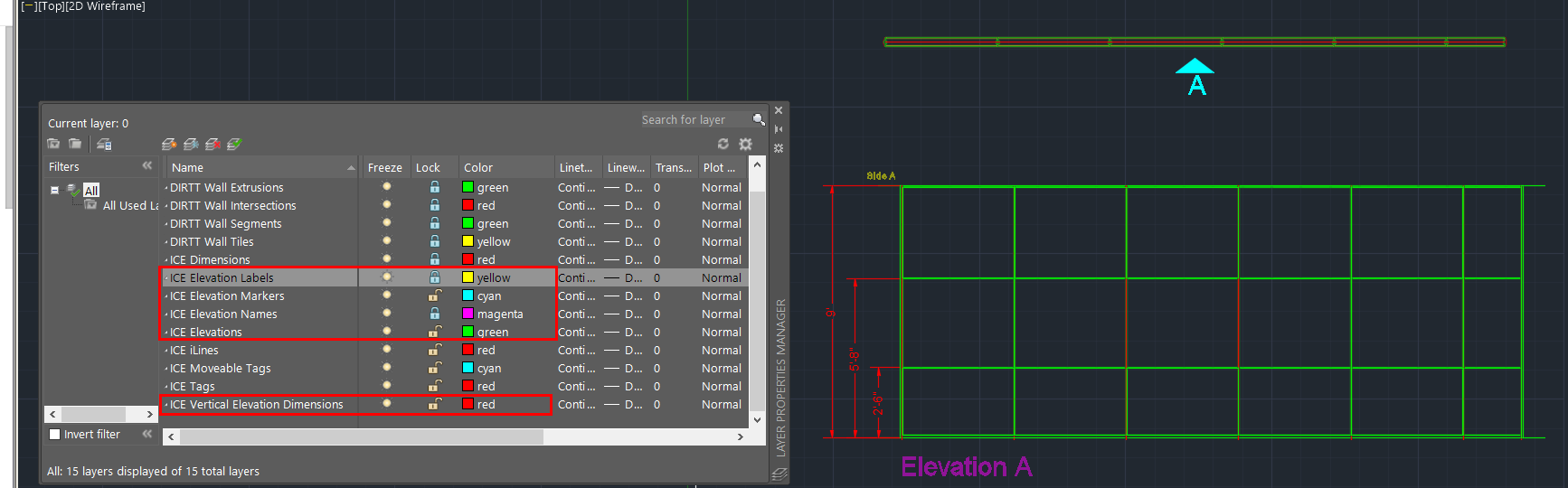
ICE Elevations
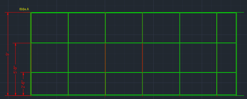
Contains the elevation. In this example image, the elevation is green:
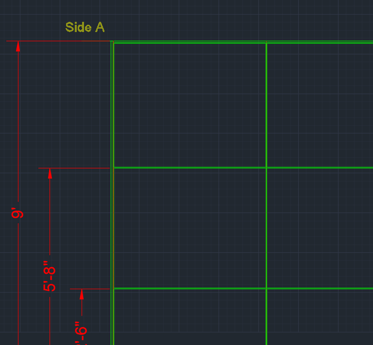
ICE Elevation Labels
Contains the elevation labels that appear above the vertical elevation dimensions. Elevation labels indicate the side of the wall that the elevation shows. In this example image, the elevation label is yellow and reads Side A:
ICE Elevation Markers
Contains the elevation markers that appear on wall segments (for example, A, B) . Elevation markers connect each side of a wall segment to a specific elevation. For example, in this image, the elevation marker A appears on the side of the wall that is represented in Elevation A:
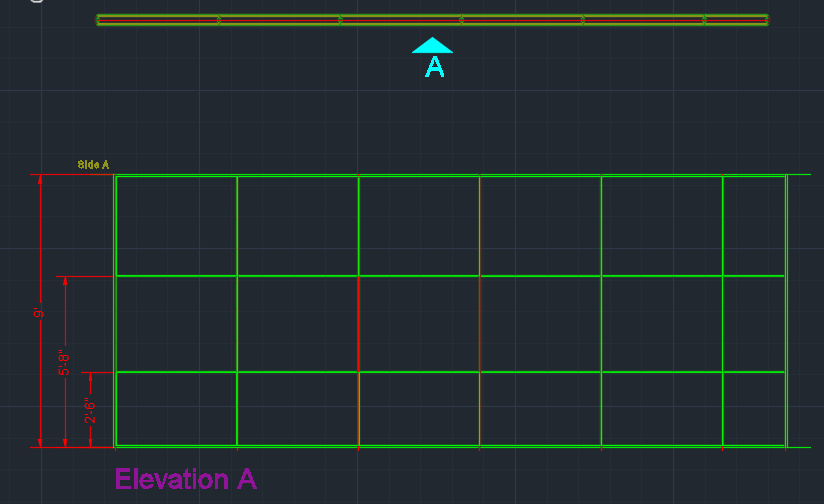
ICE Elevation Names
Contains the elevation names that appear under elevations (for example, Elevation A, Elevation B). In this example image, the elevation name is Elevation A:
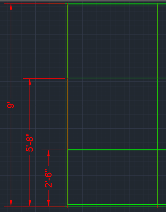
ICE Vertical Elevation Dimensions
Contains vertical dimensions for elevations. In this example image, the vertical elevation dimensions are red:
Related Links:
Topic last updated on 3/16/2023.