Next, you will create a common reference point in ICE by inserting Fixed Walls to replace two intersecting grid lines in your DWG file. The names of the gridlines may vary from project to project, but it is common practice to select the lower left-most X-axis and Y-axis gridlines in the DWG file (e.g. 1, 1 or A, A in standard grid coordinates) for inserting Fixed Walls. These walls will locate a common reference point that will help you line up your DIRTT Layout in the Base Building model in Revit later.
You will need to complete this step whether you are converting a file or coordinating files together.
1.In ICE 2D, click Layers and unlock all the layers.
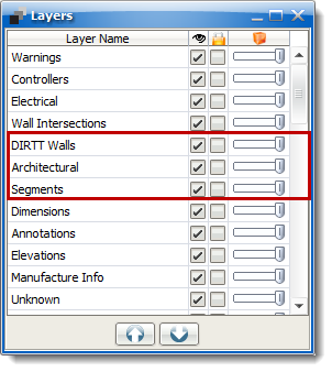
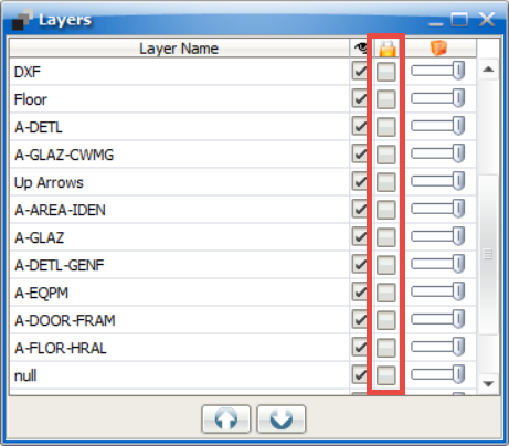
2.Exit the Layers window once complete.
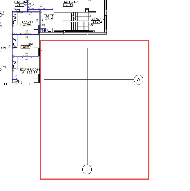
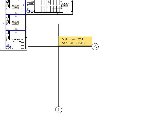
3.Hold Ctrl and click both Gridline A and Gridline 1, or the next lowest letter and number Gridlines.
4.Right-click and select Instawall.
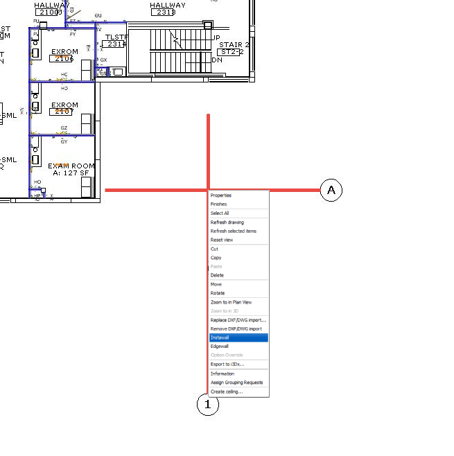
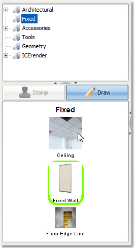
5.Navigate to the Fixed folder in the Product Palette and select Fixed Wall.
6.You should now have two Fixed Walls.
Related Links