|
Navigation: VISUALIZE > ICErender Guide > Render Styles Photo |
Scroll Prev Top Next More |
Photo Style is accessed under the Render Styles tool bar menu.
1.In the 3D window , select the Render Styles menu, then click Photo Style Settings. The following settings are found in the 3D and Render Styles tab:

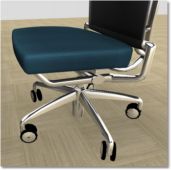
FX Finishes: When enabled, this function allows for enhanced, more detailed finishes to be displayed in the 3D view. FX Finishes include chrome, glass, aluminum, leather, etc.
Note: Enhanced finishes come from specific manufacturers, thus, this function may not work for all items in a given drawing.
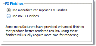
1.In the FX Finishes tab of the Style Settings window, “Use manufacturer supplied FX Finishes” is already selected by default. Select “Use no FX Finishes” then click OK at the bottom of the window to disable this function.
|
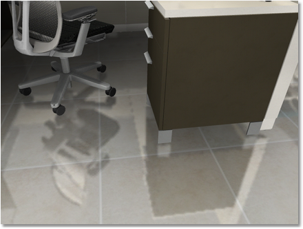
Floor Reflectivity: Controls the reflective properties of the floor in the scene. In the FX Finishes tab, locate the Floor slider. As the slider is moved to the right, the reflectivity of the floor increases. Click OK in the Styles Settings window to see the change in the 3D window.
|

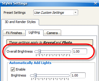
Overall Brightness: (Lighting tab) Takes into account all lighting in a scene to increase or decrease brightness.
1.Go to the Lights tab of the Styles Settings window.
2.Click and drag the Brightness slider, or enter a specific value in the field to the right of the slider.
|
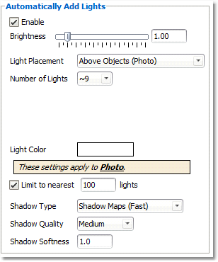
Automatically Add Lights: When enabled, allows ICErender to automatically place a specified number of lights in a scene to provide additional illumination.
Note: This applies to Reveal and Photo settings.
To enable and adjust Automatically Add Lights:
1.In the Lighting tab of the Styles Settings menu, the Automatically Add Lights function is already enabled. De-select Enable and click OK to disable this function.
2.Brightness: To modify the Brightness of the automatic lights, adjust the Brightness slider or enter a specific value, then click OK.
a.Note: Values beyond 2.00 can be very bright.
3.Light Placement: In the drop-down, select how the automatic lights will be positioned.
•Light Grid applies to Reveal and Photo only. This is the only Light Placement option that functions when rendering with Reveal Settings.The light grid places lights throughout the entire scene at a fixed height in an even, uniform, grid-like pattern.
oHeight: Enter a value to adjust the height of the lights from the floor.
oSpacing: Enter a value to adjust how far apart each automatic light is placed on the light grid. The further the spacing, the dimmer the drawing will appear.
oOffset X/Offset Y: Enter a value in either field to adjust the positioning of the light grid along the X and Y axes.
oLight Color: Click in the white rectangle to change the color of the automatic lights.
•Above Objects applies only to Photo. These lights shine down from above the model. Recommended for shots taken from further away. However, if you have a ceiling present, it will block these lights.
oNumber of Lights: approximate number of lights placed throughout the entire layout.
oLight Color: Click in the white rectangle to change the color of the automatic lights.
•In Front of Camera applies only to Photo. These lights are place in front of the camera, at a fixed height. These lights illuminate only what's close by. Recommended for “close up” shots of a particular object.
oNumber of Lights: Number of lights placed near the camera.
oHeight: Enter a value to adjust the height of the lights from the floor.
oLight Color: Click in the white rectangle to change the color of the automatic lights.
4.Limit to nearest ____ lights: When enabled, ICErender will only use the closest lights to illuminate the scene in order to save memory and maximize rendering time.
5.Shadow Type: Select the type of shadows from the drop-down menu.
•Shadow Maps (Fast): Quicker rendering time, less quality
•Area Shadows (Accurate): More quality, but may require more rendering time.
•No Shadows Shadows will not be applied.
6.Shadow Quality: Select Low, Medium, or High from the drop-down menu. NOTE: Selecting Medium or High for Shadow Maps can often give high quality shadows and render more quickly than Area Shadows.
7.Shadow Softness: Controls the definition of shadow lines. Settings below of “1” will render stark, hard shadow lines, with the “fuzziness” of the shadows increasing as the number is increased to a maximum of 10.
a.Note: “5” is a recommended setting.
|

Field of View: This is the area that is visible (as through an optical instrument).
To control Field of View:
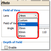
1.Select the type of lens to show a specific angle. The Lens drop-down menu has preset lens sizes to choose from.
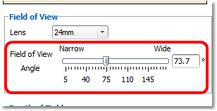
2.To use a Custom view, use the Field of View Angle slider to adjust how narrow or wide you want the visible area.
|
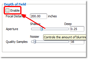
Depth of field: This is a characteristic of a camera that can be used to enhance the image composition of the photo. Depth of field means the sharp area surrounding the point of focus. The magnitude of the sharp area is affected by several factors: distance between the camera and the subject, focal length and aperture.
To control the Depth of Field:
1.Under the Camera tab, check the Enable box under Depth of Field.
2.Adjust the Focal Distance; the distance from a lens to its focus.
3.Use the Aperture slider for adjusting the shallowness and depth of how blurry the foreground and background are. The higher values have more sharpness.
4.Adjusting the Quality Samples control the quality of the blurriness of the foreground and background. The higher values are smoother, but add to rendering time.
|

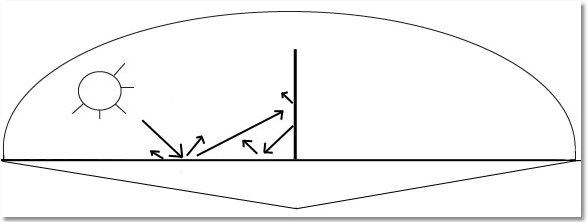
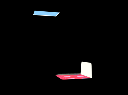
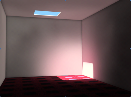
Global Illumination: ICErender uses the geometry in the scene to allow light to bounce off multiple surfaces, thereby providing more realistic, physically-based illumination for a scene. Sometimes referred to as “indirect illumination”.
The image to the left is a scene with Global Illumination disabled, and the image to the right is with Global Illumination enabled. See the “color bleeding” that occurs with Global Illumination enabled (color from the carpet bleeding onto the walls and ceiling).
Global Illumination disabled Global Illumination Enabled
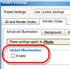
To enable Global Illumination:
1.In the Render Styles tab of the Photo Settings, click Enable to turn on Global Illumination
|
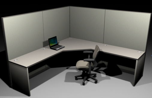
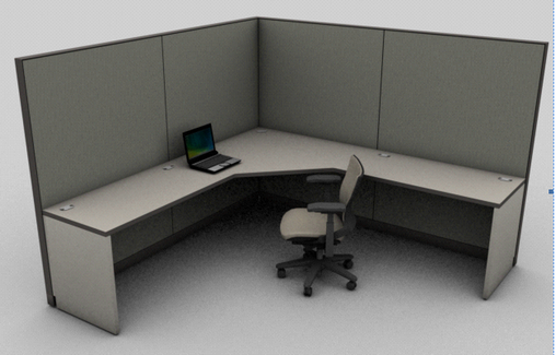
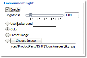
Environment Light: When enabled, this function allows ICErender to place an even, blanket of light over the whole scene.
No Environment Light Environment Light enabled
To Enable Environment Light:
1.In the Render Styles tab under Advanced Illumination, check Enable to turn on Environment Light.
2.Adjust the brightness by moving the Brightness slider.
|
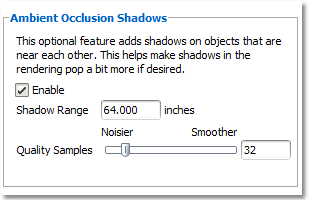
Ambient Occlusion Shadows: This function adds shadows to objects that are near each other, resulting in a crisper, more filled-out image that does not appear “flat”.
To Enable Ambient Occlusion Shadows:
1.In the Render Styles tab, under the Advanced Illumination, click Enable to turn on Ambient Occlusion.
2.Shadow Range: Represents the distance from the object that the shadow calculations include. For example, if a chair next to a wall is producing an undesirable shadow, the range can be reduced until the ideal shadow is cast. Recommended distance is between 12 and 64.
3.Quality Samples: Represents the number of samples that ICErender uses to calculate the shadows between objects. A low amount may result in more grainy shadows, but a quicker rendering time, and vice versa. Recommended value: between 32 and 128.
|

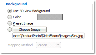
Background: (Background tab) Select a rendering background using any of the options in this section.
1.Use 3D View Background: The background in the completed rendering will remain the same as in the ICE 3D window.
2.Color: Click the color thumbnail to assign a new background color.
3.Preset Image: If a preset image was placed in the 3D window (i.e., the sky option in 3D), this image will also appear in the rendering.
Choose Image: Assign a custom .jpg image to appear as the background
|

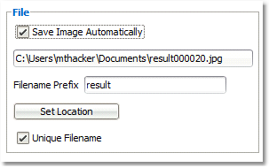
File: (Result Image tab) Use this function to automatically save renderings to a specific file location.
1.Save Image Automatically: By default, ICE will automatically save all renderings to the user’s My Documents folder. Un-check the box to prevent ICE from automatically saving renderings. NOTE: If this is done, any rendering would have to be saved manually by the user.
2.File name Prefix: All automatically saved renderings will have the prefix “result <number>”. Change the prefix by typing in the field.
3.Choose Folder: To save renderings to a location other than My Documents, click Unique File name and specify a new file location.
|
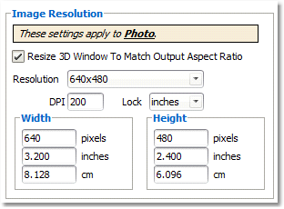
Image Resolution: This section gives various options for the final size of the rendered image.
1.Re-size 3D Window To Match Output Aspect Ratio: When this box is checked, ICE will automatically re-size the 3D window any time a new resolution is chosen (see Step 2).
2.Resolution: Click the drop-down to select the window resolution for a rendering. 1024x768 or HD are good for digital renderings, while the Custom settings are optimal for printing. If a custom resolution is desired, the values can be entered in the Width and Height fields below the Resolution drop-down.
For example: if you would like to create an 8”x10” rendering, choose “Custom” from the Resolution drop-down menu, keep 200 marked in the DPI field, and type 10 in the Width inches field, and type 8 in the Height inches field. Notice how the pixels values are updated automatically to meet the requirements of the 8”x10” rendering.
|
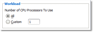
Workload: If a computer contains multiple processors, the number of processors ICErender uses can be limited by selecting Custom, in order to prevent ICErender from not sharing all the CPU power.
1.In the Main tab of the ICErender Settings, select Custom.
2.Enter the number of processors to be used.
|
Created with Help & Manual 7 and styled with Premium Pack Version 3 © by EC Software

